Acura Vigor (1992 – 1994) – fuse box diagram
Year of production: 1992, 1993, 1994
Passenger compartment fuse box
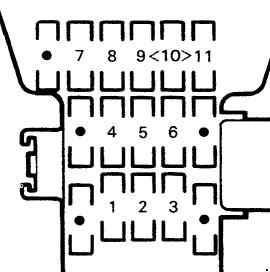 Acura Vigor – fuse box diagram – passenger compartment
| Position | Fuse rating [A] | Protected component |
| 1 | 10 | Gauge and warning indicator lights, Clock, Back-up lights, Speed sensor, Integrated control unit |
| 2 | 15 | ECU, ELD unit, Voltage regulator (IG1), Fuel pump, Fan timer unit, SRS unit (VA) |
| 3 | 10 | SRS unit (VB) |
| 4 | 7,5 | Cruise control system, A/T control unit, Security control unit |
| 5 | 10 | Sunroof relays (GS), Windshield wiper system, Shift lock solenoid |
| 6 | 30 | Windshield wiper motor, Integrated control unit |
| 7 | 7,5 | ABS system, Heater and A/C system, Option (B) ACC |
| 8 | 7,5 | Rear window defogger system, Seat heater system (CANADA), A/C system, Door mirror defogger (CANADA), Fan timer unit |
| 9 | 7,5 | ECU, Gauge (brake check circuit) |
| 10 | 7,5 | Daytime running light control unit (CANADA) |
| 11 | 10 | Cigarette lighter relay (coil), Option (A), Stereo sound system |
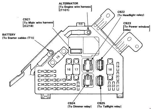
Fuse box in the engine compartment
 Acura Vigor – fuse box diagram – engine compartment
| Position | Fuse rating [A] | Protected component |
| 15 | 100 | Power Distribution |
| 16 | 40 | Rear window defogger relay (contacts) |
| 17 | 30 | Blower Motor |
| 18 | 50 | Ignition switch (BAT) |
| 19 | 20 | Left headlight, Daytime running light (CANADA) |
| 20 | 20 | Right headlight, Daytime running light (CANADA) |
| 21 | 20 | Lighting switch, Taillight relay (contacts) |
| 22 | 15 | Seat heater system (CANADA) |
| 23 | — | — |
| 24 | 20 | Right rear power window motor |
| 25 | 20 | Left rear power window motor |
| 26 | 20 | Front passenger power window motor |
| 27 | 20 | Driver’s power seat recline motor (USA – GS) |
| 28 | 20 | Driver’s power window switch, motor, and power window control unit |
| 29 | 30 | Sunroof motor (GS) |
| 30 | 20 | Horn, key interlock solenoid (A/T), Security system, Brake system |
| 31 | 20 | Driver’s power seat slide (fore/aft) motor |
| 32 | 20 | Power door lock control unit |
| 33 | 10 | ECU main relay |
| 34 | 15 | Condenser fan motor |
| 35 | 10 | Hazard lights, Turn signal/hazard relay |
| 36 | 15 | Fog lights |
| 37 | 15 | Seat heaters (CANADA), Courtesy lights, dome light, Trunk light, Power antenna motor, Integrated control unit, Rear reading lights |
| 38 | 15 | Radiator fan motor |
| 39 | 10 | ECU, Fan timer unit, A/T control unit, Clock, Stereo sound system |
ABS fuse box
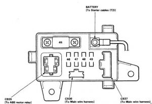 Acura Vigor – fuse box diagram – ABS fuse box
| Number | Ampere ratting [A] | Description |
| 45 | 50 | ABS motor relay (contacts) |
| 46 | 7,5 | ABS control unit |
| 47 | 15 | ABS control unit (+) B3 |
| 48 | 15 | ABS control unit (+) B2 |
| 49 | 15 | ABS control unit (+) B1 |
WARNING: Terminal and harness assignments for individual connectors will vary depending on vehicle equipment level, model, and market.