Alfa Romeo 155 (1992 – 1998) – fuse box diagram
Year of production: 1992, 1993, 1994, 1995, 1996, 1997, 1998
Fuse Panel
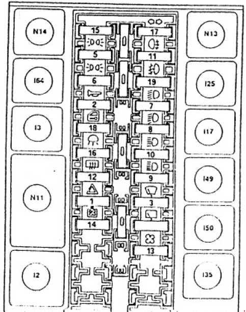
| Fuse | A | Circuit protected |
| 1 | 10 | Hazard warning lights |
| 2 | 20 | Horns, Cigar lighters, Stoplights, Boot release, Radio |
| 3 | 20 | Windscreen wipers |
| 4 | 20 | Roof light timer |
| 5 | 10 | Control lighting, Rear left and front right sidelights, RH numberptale light |
| 6 | 10 | Control lighting, Rear right and front left sidelights, LH numberptale light |
| 7 | 10 | RH dipped beam headlight |
| 8 | 10 | LH dipped beam headlight |
| 9 | 10 | RH main beam headlight |
| 10 | 10 | LH main-beam headlight (+ warning lamp) |
| 11 | 7,5 | Rear foglamp (+ warning lamp) |
| 12 | 30 | Heated rear window (+ warning lamp), Door mirror defrosters |
| 13 | 20 | Heating/air conditioning fan, Seat warming, Rear and front power windows, Radio |
| 14 | 20 | Engine cooling fan (6V) |
| 25 | Electric fan for radiator cooling | |
| 15 | 10 | Dashboard, Check Panel, Windscreen washers, Headlight washers, Reversing lights, Controlled damping suspension solenoid valves, Air conditioning compressor control, Engine electric fan control |
| 16 | 7,5 | Interior lights, Clock, Air conditioning control unit |
| 17 | 7,5 | Direction indicators, Door mirror adjustment, Controlled damping suspension |
| 18 | 20 | Door locks |
| 19 | 20 | Front foglamps (+ warning lamp) |
| Relay | ||
| N11 | Door locking control unit | |
| N13 | Hazard warning lights and direction indicators intermittence | |
| N14 | Electronic windscreen wiper intermittence | |
| I2 | Heated rear window relay | |
| I3 | Horn relay | |
| I17 | Fog-light relay | |
| I25 | Rear fog light relay | |
| I35 | Key-operated supply relay | |
| I49 | Dipped beam headlight | |
| I50 | Main beam headlight | |
| I64 | Sidelights relay | |
Auxiliary Fusebox
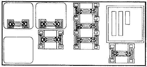
| A | Color | Circuit protected |
| 20 | Black | Headlight washer intermittence |
| 25 | Brown | Passenger side power window |
| 10 | Red | ABS |
| 25 | Blue | Rear power windows |
| 30 | Green | Electric seat adjustment |
| 30 | Red | Boot release |
| 20 | Brown | Controlled damping suspension |
| 30 | White | Sunroof |
| Black | Timer for headlight washer | |
| Green | Relay for radiator fan (only for TS model) |
1.8-2.0 TS Model
The following fuses are housed on a bracket located between the battery and the air-flow meter.
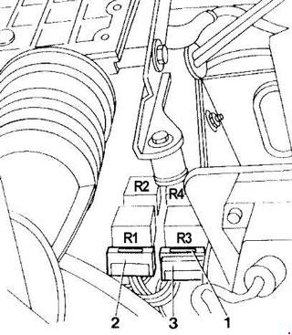
| Number | Circuit protected | |
| 1 | Control unit power supply | |
| 2 | Lambda probe (for vehicles equipped with catalytic converter) | |
| 3 | Fuel pump | |
| Relay | ||
| R1 | Fuel pump relay | |
| R2 | Main relay | |
| R3 | Timing variator relay | |
| R4 | Relay for services | |
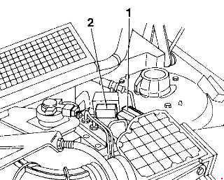
2.4 V6 model
The following fuses are located in a box located on the rear wall of the engine compartment next to the tank
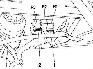
| Number | Fuse component | |
| 1 | Lambda probe (for vehicles equipped with catalytic converter) | |
| 2 | Fuel pump | |
| Relay | ||
| R1 | Fuel pump relay | |
| R2 | Main relay | |
| R3 | Relay for services | |
Heating-Ventilation System
For vehicles equipped with a heating-ventilation system, the fuses relating to the specific parts are housed in a container located on the front wall of the engine compartment.
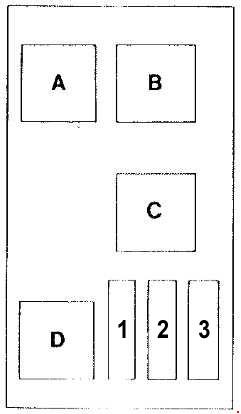
| No. | A | Fuse component |
| 1 | 30 | Passenger compartment electric fan |
| 2 | 40 | Engine cooling liquid radiator electric fan (only for 2.4 V6 model) |
| 3 | 15 | Air conditioning system compressor |
| Relay | ||
| A | Relay for engine cooling liquid radiator fan (only for 2.4 V6 model) | |
| B | Slug for engine cooling liquid radiator fan | |
| C | Relay for air conditioning compressor cut-in | |
| D | Supplementary relay | |
The following fuses are housed in the rear left-hand part of the engine compartment next to the brake-clutch fluid reservoir.
| No. | A | Fuse component |
| 1 | 50 | Heating-ventilatton system control unit |
| 2 | 40 | Engine cooling liquid radiator fan (only for 1.8 – 2.0 TS model |
WARNING: Terminal and harness assignments for individual connectors will vary depending on vehicle equipment level, model, and market.