Audi 100 (1992) – fuse box diagram
Year of production: 1992, 1993, 1994
Instrument panel fuses box
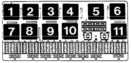
| № | A | Description |
| 1 | 15 | Rear fog lights |
| 2 | 15 | Emergency flash switch, anti-theft system (USA only) |
| 3 | 25 | Horns, brake lights switch |
| 4 | 15 | Luggage compartment, light, cigar lighter, interior lights |
| 5 | 30 | Not used |
| 6 | 5 | Tail lights, side marker light, RF |
| 7 | 5 | Tail lights, side marker light, LF |
| 8 | 10 | Headlight, hi-beam, right |
| 9 | 10 | Headlight, hi beam, left |
| 10 | 10 | Headlight, lo beam, right |
| 11 | 10 | Headlight, lo beam, left |
| 12 | 15 | Automatic transmission, backup lights, interior lights |
| 13 | 15 | Fuel pump |
| 14 | 5 | License plate lights, glove compartment light, engine compartment light, center console |
| 15 | 25 | Wipers/washer |
| 16 | 30 | Rear defogger |
| 17 | 30 | Fresh air fan, air conditioning |
| 18 | 5 | Power mirror switch |
| 19 | 10 | Central locking system, anti-theft system (USA only) |
| 20 | 30 | Heated seats |
| 21 | 25 | Fuel injection control unit, diagnostic |
| 22 | — | Open |
| 23 | — | Open |
| 24 | — | Open |
| 25 | — | Open |
| 26 | 5 | Speedometer, power mirrors |
| 27 | 10 | Ignition control unit |
| 28 | 15 | Fuel injection control unit, electronic engine cintrol |
| 29 | — | Open |
| 30 | 5 | Automatic transmission |
| № | Description |
| 1 | Rear fog light jumper plug |
| 2 | Rad. cooling fan relay 2nd stage |
| 3 | Rad. cooling fan relay after run control unit |
| 4 | Open |
| 5 | Load reduction relay |
| 6 | Open |
| 7 | Horn relay |
| 8 | Automatic transmission/anti-theft relay |
| 9 | Wash/wiper intermit, relay |
| 10 | Fuel pump relay, J17 |
| 11 | Open |
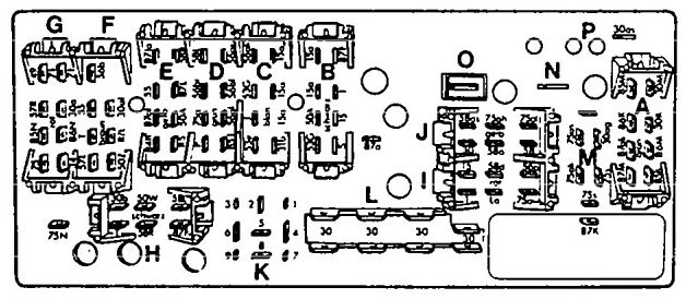
| № | Description | Color |
| A | Air conditioning connector | Gray |
| B | Right front wiring harness connector | Black |
| C | Instrument panel connector | Blue |
| D | Left front wiring harness connector | Green |
| E | Left front wiring harness connector | Yellow |
| F | Instrument panel connector | Brown |
| G | Instrument panel connector | Red |
| H | Rear wiring harness connector | Black |
| I | Instrument panel connector | Red |
| J | Instrument panel connector | Yellow |
| K | — | — |
| L | Single connector (terminal 30) connector | Colorless |
| M | For optional equipment connector | Colorless |
| N | — | — |
| O | — | — |
| P | To fuse 26 | — |
WARNING: Terminal and harness assignments for individual connectors will vary depending on vehicle equipment level, model, and market.