Audi A3 (2012 – 2016) – fuse box diagram
Year of production: 2012, 2013, 2014, 2015, 2016
Fuses in the interior
The fuses are behind the cover in the steering column area.
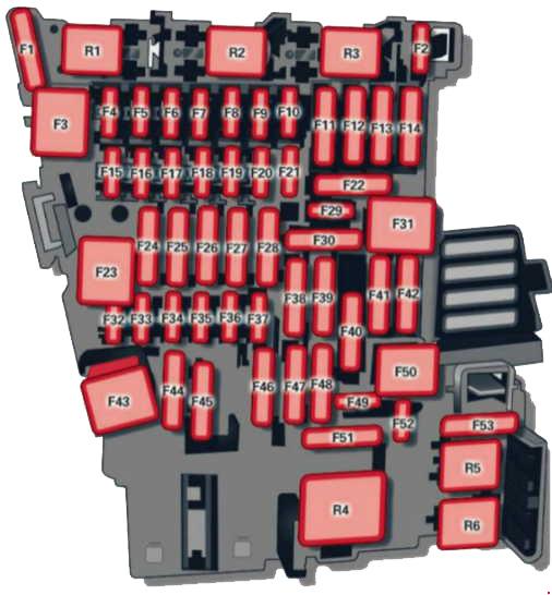
| № | Equipment |
| 1 | Engine components |
| 2 | Seat adjustment |
| 3 | Hydraulic pump cover (Cabriolet) |
| 4 | MMI control panel, MMI components |
| 5 | Gateway |
| 6 | Selector lever (automatic transmission) |
| 7 | Climate/heating control, auxiliary heating, rear window defogger relay |
| 8 | Diagnosis, electromechanical parking brake switch, light switch, rain and light sensor, interior lighting communication box (Plug-in hybrid drive*) anti-theft alarm system |
| 9 | Steering column switch module |
| 10 | Display |
| 11 | Reversible driver’s side safety belt tensioners |
| 12 | MMI area |
| 13 | Adaptive dampers control module / service plug (Plug-in hybrid drive*) |
| 14 | Climate control system blower |
| 15 | Electronic steering column lock |
| 16 | MMI area |
| 17 | Instrument cluster |
| 18 | Rearview camera |
| 19 | Convince key system control module, tank system |
| 20 | Tank system |
| 21 | – |
| 22 | – |
| 23 | Exterior lighting, heated washer fluid nozzles |
| 24 | Panorama sunroof / power top control module, power top latch (Cabriolet) |
| 25 | Door/driver’s side doors (for example power windows) |
| 26 | Seat heating |
| 27 | Sound-amplifier |
| 28 | Power top control module, electronics (Cabriolet) |
| 29 | Interior lights |
| 30 | – |
| 31 | Exterior lighting |
| 32 | Driver assistance systems |
| 33 | Airbag |
| 34 | Button illumination, coils for upper cabin heating relay (Cabriolet) and socket relay, interior sound, reversing light switch, temperature sensor |
| 35 | Function lighting, diagnosis, headlight range control system, air quality sensor, automatic dimming rearview mirror |
| 36 | Right cornering light / right LED-headlight |
| 37 | Left cornering light / left LED-headlight |
| 38 | High-voltage battery (Plug-in hybrid drive*) |
| 39 | Door/front passenger’s side doors (for example, power windows) |
| 40 | Sockets |
| 41 | Reversible front passenger’s side safety belt tensioners |
| 42 | Central locking components, windshield washer system |
| 43 | Fleadlights, lighting |
| 44 | All wheel drive |
| 45 | – |
| 46 | – |
| 47 | Rear window wiper |
| 48 | Outer noise amplifier (Plug-in hybrid drive*) |
| 49 | Starter, clutch sensor, headlight relay coil, high-voltage battery (Plug-in hybrid drive*) |
| 50 | – |
| 51 | – |
| 52 | – |
| 53 | Rear window defogger |
| The power seats* are protected via circuit breakers that automatically switch on after a few seconds after the overload has been reduced. | |
Fuses in the engine compartment
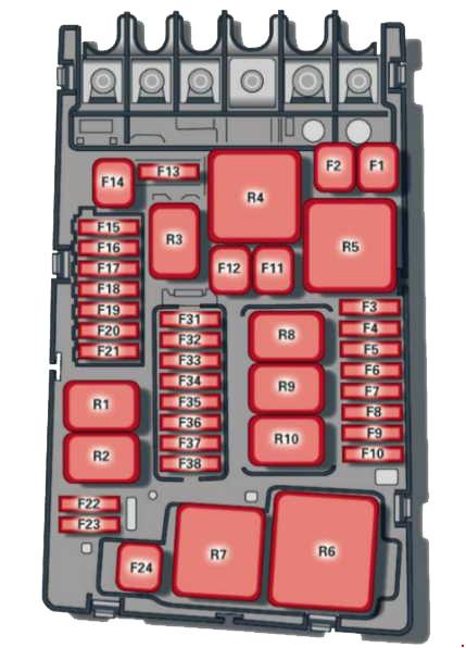
| № | Equipment |
| 1 | ESC control module |
| 2 | ESC control module |
| 3 | Engine control module (gasoline/diesel) |
| 4 | Engine cooling, engine components, auxiliary heater coil relay (1+2), secondary air injection pump relay |
| 5 | Engine components, tank system |
| 6 | Brake light sensor |
| 7 | Engine components, water pumps |
| 8 | Oxygen sensor |
| 9 | Engine components, exhaust door, glow time control module, SULEV valve |
| 10 | Fuel injectors, fuel control module |
| 11 | Auxiliary heater heating element 2 |
| 12 | Auxiliary heater heating element 3 |
| 13 | Automatic transmission control module |
| 14 | – |
| 15 | Horn |
| 16 | Ignition coil/power electronics (Plug-in hybrid drive*) |
| 17 | ESC control module, engine control module |
| 18 | Terminal 30 (reference voltage) |
| 19 | Windshield wipers |
| 20 | Horn |
| 21 | – |
| 22 | Terminal 50 diagnosis |
| 23 | Starter |
| 24 | Auxiliary heater heating element 1, brake booster (Plug-in hybrid drive*) |
| 25 | – |
| 26 | – |
| 27 | – |
| 28 | – |
| 29 | – |
| 30 | – |
| 31 | Vacuum pump/water pump (Plug-in hybrid drive*) |
| 32 | LED headlights |
| 33 | Brake booster memory (Plug-in hybrid drive*) |
| 34 | Brake booster control (Plug-in hybrid drive*) |
| 35 | Relay (Plug-in hybrid drive*) |
| The power seats* are protected via circuit breakers that automatically switch on after a few seconds after the overload has been reduced. | |
WARNING: Terminal and harness assignments for individual connectors will vary depending on vehicle equipment level, model, and market.