Audi RS6 (C5; 1997 – 2005) – fuse box diagram
Year of production: 1997, 1998, 1999, 2000, 2001, 2002, 2003, 2004, 2005
Fuse box driver side dash panel
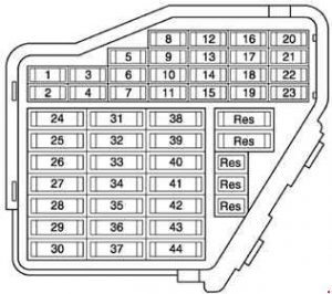
| No. | A | Fused function |
| 1 | 5 | Heater element, left washer jet Heater element, right washer jet |
| 2 | 10 | Hazard warning light switch |
| 3 | 5 | Glove box light |
| 4 | 5 | Number plate light |
| 5 | 10 | Oil level/oil temperature sender Compressor regulating valve, air conditioning system High pressure sender Tiptronic switch Tyre pressure monitor control unit Bulb monitoring device Mobile phone operating electronics control unit Control and display unit for air conditioner/Climatronic Air quality sensor Navigation system with CD drive control unit Self-levelling suspension control unit Operating unit to control suspension height Telephone/telematics control unit Control unit for voice control Parking aid control unit Rear roller blind switch |
| 6 | 5 | Central locking control unit |
| 7 | 10 | ABS control unit Steering angle sender TCS/ESP button Cruise control system brake pedal switch (diesel direct injection system) Clutch pedal switch |
| 8 | 5 | Telephone/telematics control unit Control unit for voice control |
| 9 | 10 | Heated exterior mirror, driver’s side Heated exterior mirror, front passenger’s side |
| 10 | 5 | Headlight range control, control unit |
| 11 | 5 | Automatic anti-dazzle interior mirror |
| 12 | 10 | Diagnosis connection |
| 13 | 10 | Brake light switch Brake light bulbs |
| 14 | 10 | Central locking control unit Memory operating unit, driver’s seat Memory operating unit, front passenger’s seat Luggage compartment release switch Interior monitor switch |
| 15 | 10 | Control unit with display in dash panel insert Solar cell isolation relay Navigation system with CD drive control unit Mirror memory control unit Auxiliary heating radio controlled receiver |
| 16 | 5 | Steering angle sender |
| 17 | 10 | Tyre pressure monitor control unit Self-levelling suspension control unit Two-way radio switch Parking aid control unit |
| 18 | 10 | Main beam bulb, right Main beam warning lamp |
| 19 | 10 | Main beam bulb, left |
| 20 | 15 | Dipped beam bulb, right Headlight range control motor, right |
| 21 | 15 | Dipped beam bulb, left Headlight range control motor, left |
| 22 | 5 | Side light bulb, right Tail light bulb, right |
| 23 | 5 | Side light bulb, left Tail light bulb, left |
| 24 | 25 | Automatic intermittent wash/wipe relay Intermittent wiper control |
| 25 | 30 | Control and display unit for air conditioner/Climatronic Solar cell isolation relay Fresh air blower Magnetic coupling relay Auxiliary heater relay |
| 26 | 30 | Control and display unit for air conditioner/Climatronic Heated rear window switch |
| 27 | 15 | Heated steering wheel Rear window wiper motor |
| 28 | 20 | Fuel pump (pre-supply pump) Fuel pump control unit Fuel pump relay |
| 29 | 30 20 | Ignition coil with output stage (engine code BAS) Motronic control unit (engine code BAS) Output stage Ignition coil with output stage Motronic control unit Camshaft timing adjustment valves |
| 30 | 20 | Sliding sunroof adjustment control unit |
| 31 | 15 | Starter inhibitor and reversing light relay Hazard warning light switch Reversing light switch Diagnosis connection Multi-function switch Ignition cut-off delay relay Automatic gearbox control unit |
| 32 | 20 | Injectors Cruise control system switch |
| 33 | 15 | Cigarette lighter Cigarette lighter, rear |
| 34 | 15 | Secondary air pump relay Solenoid valves Secondary air inlet valve Turbocharger divert air valve Air mass meter Heater for lambda probes Intake manifold change-over valve |
| 35 | 30 | Trailer socket |
| 36 | 15 | Front and rear fog light switch |
| 37 | 20 | Radio Amplifier with bass loudspeaker Aerial selection control unit Operating electronics control unit, navigation Navigation/TV tuner Navigation interface Chip card reader unit |
| 38 | 20 | Central locking control unit |
| 39 | 15 | Hazard warning light switch |
| 40 | 25 | Dual tone horn relay |
| 41 | 25 | Relay for ABS solenoid valves (allroad models) |
| 42 | 25 | ABS control unit |
| 43 | 5 | Radio Operating electronics control unit, navigation |
| 44 | 30 | Auxiliary heater relay Solar cells isolation relay 2 Heated driver’s seat regulator Heated front passenger’s seat regulator Heated rear left seat switch with regulator Heated rear right seat switch with regulator |
13-point relay carrier, behind driver’s storage compartment
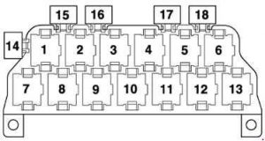
| No. | Function |
| 1 | Dual tone horn relay (telematics – USA) – J4 |
| 2 | Alternator cut-in relay – J442 Alarm system control unit (taxi) – J85 Siren relay (police vehicles) – J408 Alarm system relay, light change-over (special vehicles) – J549 |
| 3 | Solar cell isolation relay – J309 Alarm system control unit (taxi) – J85 Siren relay (police vehicles) – J408 Alarm system relay 2, intermittent main beam (special vehicles) – J461 |
| 4 | Starter inhibitor relay – J207 Starter inhibitor and reversing light relay – J226 |
| 5 | Magnetic coupling relay – J44 Auxiliary heater relay – J8 |
| 6 | Fog light relay – J5 Fuel pump relay (TDI engines) – J17 |
| 7 | Multi-function steering wheel control unit – J453 |
| 8 | Multi-function steering wheel control unit – J453 |
| 9 | Bulb monitoring device – J123 |
| 10 | Bulb monitoring device – J123 |
| 11 | Exterior mirror fold system control unit – J351 |
| 12 | Exterior mirror fold system control unit – J351 |
| 13 | Servotronic control unit – J236 |
| 14 | Taximeter fuse – S182 Fuse E (police vehicles) – S201 Hydraulic pump relay fuse (allroad models) – S279 |
| 15 | Not used |
| 16 | Alarm system fuse (taxi) – S57 Fuse B (police vehicles) – S202 |
| 17 | Taximeter and alarm system fuse (taxi) – S183 Fuse C (police vehicles) – S203 Intercom system fuse (special vehicles) – S253 Fog light fuse (daytime driving lights – Canada) – S28 |
| 18 | Fitted at any vacant points Alternator cut-in relay – J442 (special vehicles) Alarm system II control unit – J430 (taxi) Flasher relay for main beam headlight alarm system – J182 (police vehicles) Solar cell isolation relay – J309 (taxi) |
Micro-central electrics, behind driver’s storage compartment
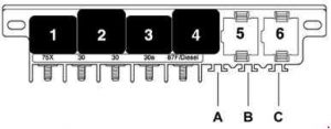
| No. | Function |
| 1 | Dual tone horn relay – J4 |
| 2 | X contact relief relay – J59 |
| 3 | Low range gearing hydraulic pump relay (allroad models) – J555 |
| 4 | Fuel pump relay (petrol engines) – J17 Relay for glow plugs (diesel engines) – J52 |
| 5 | Automatic intermittent wash/wipe relay – J31 |
| 6 | Automatic intermittent wash/wipe relay – J31 |
| A | Steering column adjustment fuse – S275 |
| B | Rear roller blind fuse – S100 |
| C | Alarm system 2 fuse (taxi) – S181 Fuse C (police vehicles) – S204 Fuse for rear lid emergency release (special vehicles) – S195 Multi-function steering wheel fuse (blue) – S326, phased in from 05.02 onwards |
8-point relay carrier, behind driver’s storage compartment, behind micro-central electrics (left-hand drive vehicles)
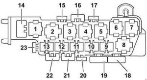
| No. | Function |
| 1 | Relay for solenoid valves – ABS with ESP – J106 |
| 2 | Radiator fan 2nd speed relay – J101 |
| 3 | Radiator fan relay – J26 Continued coolant circulation relay – J151 |
| 4 | Radiator fan run-on relay – J138 |
| 5 | Not used |
| 6 | Self-levelling suspension compressor relay (allroad models) – J403 |
| 7 | Return flow pump relay – ABS with ESP – J105 |
| 8 | Coolant shut-off valve relay – J541 |
| 14 | Seat adjustment thermo-fuse, driver’s side (allroad models) – S44 |
| 15 | Fuse for 12 V socket – S184 |
| 16 | Front electric window thermo-fuse – S37 |
| 17 | Rear electric window thermo-fuse – S43 |
| 18 | ABS control unit fuse – S123 |
| 19 | Radiator fan fuse – S42 |
| 20 | Radiator fan control unit fuse – S142 |
| 21 | Seat adjustment thermo-fuse, driver’s side – S44 Radiator fan fuse (allroad models) – S42 |
| 22 | Self-levelling suspension fuse – S110 |
| 24 | Seat adjustment thermo-fuse, front passenger’s side – S80 |
| Fitted at any vacant position: Vermin repellent system fuse – S165 | |
8-point relay carrier, behind driver’s storage compartment, behind micro-central electrics (right-hand drive vehicles)
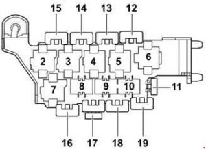
| No. | Function |
| 2 | Self-levelling suspension compressor relay (allroad models) – J403 |
| 3 | Radiator fan run-on relay – J138 |
| 4 | Relay for solenoid valves – ABS with ESP – J106 |
| 5 | Radiator fan relay – J26 |
| 6 | Return flow pump relay – ABS with ESP – J105 |
| 7 | Radiator fan 2nd speed relay – J101 |
| 8 | Not used |
| 9 | Not used |
| 10 | Not used |
| 11 | Self-levelling suspension fuse – S110 Seat adjustment thermo-fuse, front passenger’s side – S80 (RS6 models) |
| 12 | Seat adjustment thermo-fuse, front passenger’s side – S80 Radiator fan fuse – S142 (RS6 models) |
| 13 | Front electric window thermo-fuse – S37 |
| 14 | Rear electric window thermo-fuse – S43 |
| 15 | Seat adjustment thermo-fuse, driver’s side – S44 |
| 16 | Radiator fan fuse – S42 |
| 17 | Radiator fan control unit fuse – S142 Fuse for 12 V socket – S184 (RS6 models) |
| 18 | ABS control unit fuse – S123 |
| 19 | Fuse for 12 V socket – S184 |
Relay carrier, driver’s side, behind dash panel at central carrier
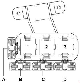
| No. | Function |
| 1 | Low heat output relay – J359 Brake servo relay – J569 |
| 2 | Auxiliary heater relay – J8 Solar cells isolation relay 2 – J354 |
| 3 | High heat output relay – J360 |
| A | Not used |
| B | Not used |
| C | Additional heater fuse 2 – S143 Hydraulic pump relay fuse (brake servo) – S279 Fuel pump fuse – S81 (RS6 models; left-hand drive vehicles) |
| D | Additional heater fuse – S109 Fuel pump fuse – S81 (RS6 models; right-hand drive vehicles) |
3-point relay carrier in electronics box, plenum chamber
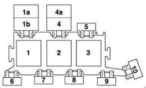
| No. | Function |
| 1 | Secondary air pump relay – J299 (RS6 models) |
| 1a | Radiator fan relay (allroad models) – J26 |
| 1b | Continued coolant circulation relay (allroad models) – J151 Additional coolant pump relay – J496 |
| 2 | Secondary air pump relay – J299 |
| 3 | Motronic current supply relay (petrol engines) – J271 Diesel direct injection system relay (diesel engines) – J322 Ignition cut-off delay relay (automatic gearbox 01J) – J64 |
| 4 | Fuel cooling pump relay – J445 Continued coolant circulation relay – J151 (RS6 models) |
| 4a | Not used |
| 5 | Engine control unit fuse – S102 Engine electronics fuse (allroad models) – S282 |
| 6 | Not used (left-hand drive vehicles) Fuse 2 for glow plugs – engine, V6 TDI, V8 TDI – S125 Fuse for glow plugs – engine, 4-cylinder – S39 Radiator fan fuse (allroad models) – S94 |
| 7 | Fuse for glow plugs – engine, V6 TDI, V8 TDI – S39 Secondary air pump fuse (petrol engines) – S130 Auxiliary heater fuse – S62 (right-hand drive vehicles) up to model year 2000 Not used (right-hand drive vehicles) |
| 8 | Auxiliary heater fuse – S62 (left-hand drive vehicles) up to model year 2000 Not used (left-hand drive vehicles |
| 9 | Fuse 2 for glow plugs – engine, V6 TDI, V8 TDI – S125 Fuse for glow plugs – engine, 4-cylinder – S39 Radiator fan fuse (allroad models) – S94 Coolant pump fuse (RS6 models) – S78 Not used (right-hand drive vehicles) |
| 10 | Fuse for fuel cooling – S262 Fuse -1- (15) (automatic gearbox 01J) – S199 Radiator fan control unit fuse (allroad models) – S142 Not used (right-hand drive vehicles) |
Fuses not in relay carrier:
Left-hand drive vehicles:
– From model year 2001 onwards auxiliary heater fuse not in electronics box – S62
Right-hand drive vehicles:
– From model year 2001 onwards auxiliary heater fuse not in electronics box – S62
– Fuse for fuel cooling – S262
– Fuse -1- (15) (automatic gearbox 01J) – S199
– Radiator fan control unit fuse (allroad models) – S142
Fuse in plenum chamber
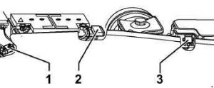
| No. | Function |
| 1 | Fuse -1- (30) (applies to V8 only) – S204 |
| 2 | Fuse -2- (30) – S205 |
| 3 | Auxiliary heater fuse – S62 |
Fuse in plenum chamber (RS6 models)
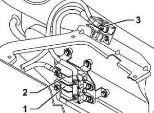
| No. | Function |
| 1 | Fuse -2- (30) – S205 |
| 2 | Fuse -1- (30) – S204 |
| 3 | Battery screw connection |
The fuses are located below coolant expansion tank.
WARNING: Terminal and harness assignments for individual connectors will vary depending on vehicle equipment level, model, and market