Audi S3 (2009) – fuse box diagram
Year of production: 2009
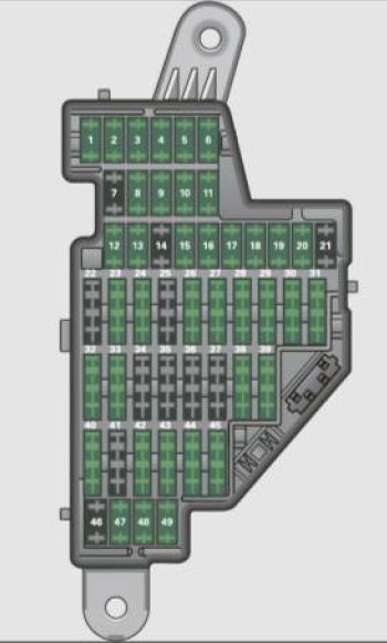
Instrument panel
| Number | Equipment | Ampere rating [A] |
| 1 | Manual headlight beam adjustment, automatic headlight beam adjustment, AFS control module, engine components, light switch (switch lighting/illumination), diagnosis socket | 10 |
| 2 | Automatic transmission, control module for CAN data transfer (gateway), electro -mechanical steering, shift gate automatic transmission engine relay, fuel tank control unit, engine control unit, brakes control (ABS), Electronic Stabilization Program (ESP), Anti -Slip Regulation (ASR), brake light switch | 10 |
| 3 | Airbag | 5 |
| 4 | Air-conditioning (pressure sensor, air quality sensor), button for Electronic Stabilization Program (ESP), Anti-Slip Regulation (ASRI, oil level sensor (WIVl, back-up light switch, front seat heating, Seat-occupancy recognition (on USA vehicles), navigation, garage door opener, automatic mirror dimming, Heated windshield washer nozzles,air conditioning (control module | 5 |
| 5 | AFS headlights (left side) | 5 |
| 6 | AFS headlights (right side) | 5 |
| 7 | — | — |
| 8 | — | — |
| 9 | — | — |
| 10 | — | — |
| 11 | — | — |
| 12 | Central locking (front doors) | 10 |
| 13 | Central locking (rear doors) | 10 |
| 14 | Electronic Stabilization Program (ESP) (control module), shift gate automatic transmission | 10 |
| 15 | Interior lights, reading lights | 10 |
| 16 | Diagnostic connector, rain sensor, air conditioning (control module), tire pressure monitor display (control module) | 10 |
| 17 | Anti -theft alarm warning system | 5 |
| 18 | Terminal 15 | 5 |
| 19 | All Wheel Drive | 10 |
| 20 | Magnetic ride | 5 |
| 21 | — | — |
| 22 | Blower fan | 40 |
| 23 | Driver’s side power window, front | 30 |
| 24 | Power outlet front | 20 |
| 25 | Rear window defogger | 30 |
| 26 | Power outlet in luggage compartment | 20 |
| 27 | Fuel tank control module, fuel pump | 15 |
| 28 | Power window , rear | 30 |
| 29 | — | — |
| 30 | — | — |
| 31 | Automatic transmission (vacuum pump) | 20 |
| 32 | Headlight washer system | 30 |
| 33 | Sliding/pop-up roof | 20 |
| 34 | — | — |
| 35 | — | — |
| 36 | Lumbar support | 10 |
| 37 | Heated seats, front | 20 |
| 38 | Passenger side power window, front | 30 |
| 39 | Special function interface | 5 |
| 40 | Starter | 40 |
| 41 | Rear window wiper | 15 |
| 42 | Windshield wiper (washer pump) | 15 |
| 43 | Convenience electronics (control module) | 20 |
| 44 | Trailer control module | 20 |
| 45 | Trailer control module | 15 |
| 46 | — | — |
| 47 | Cell phone package (VDA interface) | 5 |
| 48 | — | — |
| 49 | — | — |
Engine compartment
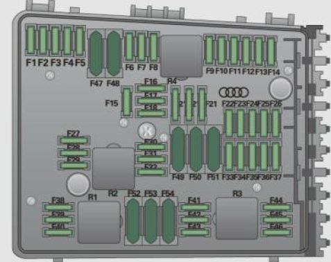
Variation (1) with 30 Plug-in Fuses
| Number | Equipment | Ampere rating [A] |
| F1 | — | — |
| F2 | Steering wheel electronics | 5 |
| F3 | Battery voltage | 5 |
| F4 | ESP valves, Anti -lock brake system (ABS) valves | 20 |
| 30 | ||
| F5 | Transmission control module | 15 |
| F6 | Steering wheel electronics, instrument cluster | 5 |
| F7 | Transmission control module | 30 |
| F8 | Navigation system, radio system | 15 |
| 25 | ||
| F9 | Navigation system, digital radio, cell phone, TV equipment | 5 |
| F10 | Engine control module, main relay | 5 |
| 10 | ||
| F11 | — | — |
| F12 | Control module for CAN data transfer (gateway) | 5 |
| F13 | Engine control module | 15 |
| 25 | ||
| F14 | Ignition coils | 20 |
| F15 | Tank diagnosis, oxygen sensor | 10 |
| 15 | ||
| F16 | Vehicle electrical system control unit (right) | 30 |
| F17 | Horn | 15 |
| F18 | Audio amplifier | 30 |
| F19 | Front windshield wiper system | 30 |
| F20 | Water return -flow pump, volume regulator valve | 10 |
| 20 | ||
| F21 | Oxygen sensor, vacuum pump | 15 |
| F22 | Clutch pedal switch, brake light switch | 5 |
| F23 | Engine relays, engine components | 5 |
| 10 | ||
| 15 | ||
| F24 | Engine components, water return-flow pump | 10 |
| F25 | Pump (ESP/ABS), ABS valve | 30 |
| 40 | ||
| F26 | Vehicle electrical system control unit (left) | 30 |
| F27 | Secondary air pump | 40 |
| F28 | — | — |
| F29 | Fuse assignment in the left-side instrument panel (special equipment) | 50 |
| F30 | Power supply relay terminal 15 | 50 |
Variation (2) with 54 Plug-in Fuses
| Number | Equipment | Ampere rating [A] |
| F1 | Vehicle electrical system control unit (right) | 30 |
| F2 | ESP valves, Anti -lock brake system (ABS) valves | 20 |
| 30 | ||
| F3 | — | — |
| F4 | Battery voltage | 5 |
| F5 | Horn | 15 |
| F6 | Engine components, fuel pump | 15 |
| F7 | — | — |
| F8 | — | — |
| F9 | Engine components | 10 |
| F10 | Fuel tank control, mass air flow sensor | 10 |
| F11 | Oxygen sensors, in front of catalytic converter | 10 |
| F12 | Oxygen sensors, behind catalytic converter | 10 |
| F13 | Automatic transmission | 15 |
| F14 | — | — |
| F15 | Water return-flow pump | 10 |
| F16 | Volume control valve | 20 |
| F17 | Steering wheel electronics, instrument cluster | 5 |
| F18 | Audio amplifier | 30 |
| F19 | Navigation system, radio system | 15 |
| 25 | ||
| F20 | Navigation system, digital radio, cell phone, TV equipment | 5 |
| F21 | — | — |
| F22 | — | — |
| F23 | Engine control modu le, main relay | 10 |
| F24 | Control module for CAN data transfer (gateway) | 5 |
| F25 | — | — |
| F26 | — | — |
| F27 | — | — |
| F28 | Engine control module | 15 |
| 25 | ||
| F29 | Engine relays, eng ine components | 5 |
| F30 | — | — |
| F31 | Front windshield wiper system | 30 |
| F32 | — | — |
| F33 | — | — |
| F34 | — | — |
| F35 | — | — |
| F36 | — | — |
| F37 | — | — |
| F38 | Engine components | 10 |
| F39 | Clutch pedal switch, brake light switch | 5 |
| F40 | Ignition coils | 20 |
| F41 | — | — |
| F42 | — | — |
| F43 | Ignition coils | 30 |
| F44 | — | — |
| F45 | — | — |
| F46 | — | — |
| F47 | Left-side lighting (electric system control unit) | 30 |
| F48 | Pump (ESP/ABS), ABS valve, Anti-lock brake systern (ABS) valves | 30 |
| 40 | ||
| F49 | — | — |
| F50 | — | — |
| F51 | Secondary air pump | 40 |
| F52 | Power supply relay terminal 15 | 50 |
| F53 | Fuse assignment in the left-side instrument panel (special equipment) | 50 |
| F54 | — | — |
WARNING: Terminal and harness assignments for individual connectors will vary depending on vehicle equipment level, model, and market.