Audi TTS Coupe (2016 – 2017) – fuse box diagram
Year of production: 2016, 2017
Instrument panel
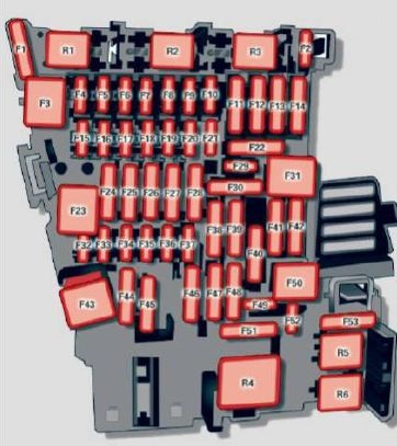
| Number | Equipment |
| F1 | Power top control modu le (Roadster) |
| F2 | Power top control modu le (Roadster) |
| F3 | ESC control module |
| F4 | Central computer processor (MIB-2) |
| F5 | Gateway |
| F6 | Anti-theft alarm system |
| F7 | Climate control system, selector lever (automatic transmission), parking heater, rear window heater relay coil |
| F8 | Diagnosis, electrical parking brake switch, light switch, rain/light sensor, interior lighting |
| F9 | Steering column switch module |
| F10 | Display |
| F11 | Haldex clutch |
| F12 | MMI area |
| F13 | Adaptive dampers control module |
| F14 | Climate control system blower |
| F15 | Electronic steering column lock |
| F16 | MMI components, safety belt microphone (Roadster) |
| F17 | Instrument cluster |
| F18 | Rearview camera |
| F19 | Convenience key system control module |
| F20 | Power lumbar support adjustment |
| F22 | Front passenger’s side upper cabin heating (Roadster) |
| F23 | Right exterior lighting, on-board computer (right) |
| F25 | Driver’s side door (for example power windows) |
| F26 | Seat heating |
| F28 | AMI High media port |
| F29 | On-board computer |
| F31 | Left on-board computer |
| F32 | Driver assistance systems |
| F33 | Airbag |
| F34 | Socket relay, interior sound, back-up light switch, temperature sensor, oil level sensor |
| F35 | Diagnosis, headlight range control system, air quality sensor, automatic dimming rearview mirror |
| F36 | Right cornering light/ right LED-headlight |
| F37 | Left cornering light/ left LED-headlight |
| F38 | Engine control module, ESC control module |
| F39 | Front passenger’s side door (for example power windows) |
| F40 | Cigarette lighter, sockets |
| F41 | SCR relay and delivery unit |
| F42 | Central locking area |
| F43 | On-board computer |
| F45 | Power adjustable driver’s side seat |
| F46 | Driver’s side upper cabin heating (Roadster) |
| F49 | Starter, clutch sensor |
| F50 | ESC valves |
| F53 | Rear window defogger |
Engine compartment
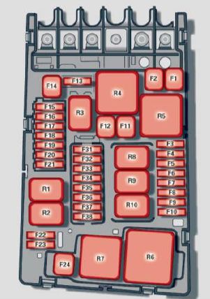
| Number | Equipment |
| F1 | ESC control module |
| F2 | ESC control module |
| F3 | Engine control module |
| F4 | Engine cooling, engine components, auxiliary heater coil relay (1+2), secondary air injection pump relay |
| F5 | Engine components, tank system |
| F6 | Brake light sensor |
| F7 | Engine components |
| F8 | Oxygen sensor |
| F9 | Engine components, exhaust door, glow time control module |
| F10 | Fuel injectors, fuel control module |
| F11 | Auxiliary heater heating element 2 |
| F12 | Auxiliary heater heating element 3 |
| F13 | Automatic transmission cont rol module |
| F15 | Horn |
| F16 | Ignition coil |
| F17 | ESC control module , engine control module |
| F18 | Terminal 30 (reference voltage) |
| F19 | Windshield wipers |
| F20 | Horn |
| F22 | Terminal SO diagnos is |
| F23 | Starter |
| F24 | Auxiliary heater heating element 1 |
| F32 | LED headlights |
WARNING: Terminal and harness assignments for individual connectors will vary depending on vehicle equipment level, model, and market.