Buick Skylark (1980 – 1985) – fuse box diagram
Year of production: 1980, 1981, 1982, 1983, 1984, 1985
Fuse box diagram
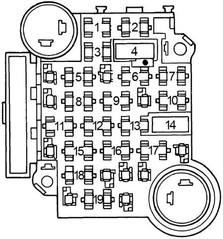
| Fuse | [A] | Protected Component |
| 1 | 5 | Instrument panel, lights on reminder and console light |
| 2 | 20 | Choke heater and cooling fan |
| 3 | — | — |
| 4 | 30 | Circuit breaker: Power windows |
| 5 | — | — |
| 6 | 25 | Air conditioning blower and compressor, heater and trunk release |
| 7 | 10 | Electronic Control Module |
| 8 | — | — |
| 9 | — | — |
| 10 | 20 | Stop and hazard lights |
| 11 | 20 | Air conditioning, defogger, seat belt warning, charge indicator and computer command control |
| 12 | 20 | Front parking and marker lights. Rear parking, marker and license lights |
| 13 | — | — |
| 14 | 30 | Circuit breaker: Defogger, power door locks and power seats |
| 15 | 20 | Back-up and turn signal lights, and Idle stop solenoid |
| 16 | 20 | Air conditioning, cigar lighter, clock, courtesy, trunk and vanity lights, ignition key warning buzzer, lights on reminder, power antenna, power door locks and radio capacitor |
| 17 | — | — |
| 18 | 10 | Radio, cruise control and power antenna |
| 19 | 25 | Windshield wiper/washer and wiper/washer delay |
| Circuit Breaker: Headlight Circuit — A thermo circuit breaker is incorporated in the headlight switch assembly to protect headlight circuits. | ||
WARNING: Terminal and harness assignments for individual connectors will vary depending on vehicle equipment level, model, and market.