Cadillac Fleetwood (1996) – fuse box diagram
Year of production: 1996
Instrument panel fuse block
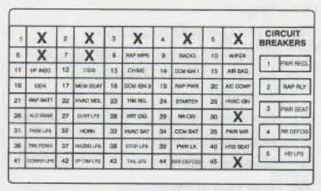
| Fuse number | Usage |
| 8 | Component Center (RAP Wiper) Relay |
| 9 | Radio Receiver |
| 10 | Windshield Wiper/Washer Switch |
| 11 | Air Bug System, Instrument Panel Cluster |
| 12 | ParK/Neutral Position and Backup Lamp Switch, Turn Signal Lamp Flasher |
| 13 | Warnin Alarm Cruise Control Release Switch, Inside Rearview Mirror, Rear window Defogger Relay, Park/Neutral Position and Backup Lamp Switch, Automatic Level Control Sensor |
| 14 | Central Control Module (CCM) |
| 15 | Air bag System |
| 16 | Generator, Secondary Engine Cooling Fan Relay |
| 17 | Driver’s Seat Ad’uster Memory Module, Heated Driver’s Seat Switch, Heated 4 assenger’s Seat Swltch |
| 18 | Central Control Module (CCM), Remote Control Door Lock Reciver and Theft-Deterrent Module, Cruise Control Module, Cruise Control Switch, Cruise Release Switch |
| 19 | Accessory Time Delay Cut-Off (RAP Power) Relay |
| 20 | A/C Compressor Relay, Primary Engine Cooling Fan Relay |
| 21 | Component Center (RAP Wiper) Relay |
| 22 | Blower Motor Control Module |
| 23 | Rear Compartment Lid Release Switch |
| 24 | Theft-Deterrent Relay, Air Bag System |
| 25 | Instrument Cluster, Heater-A/C Control, Vacum/Electric Solenoid, Electric Actuator |
| 26 | Automatic Level Control Sensor, Rear Compartment Courtesy Lamp |
| 27 | Compartment Center Relay |
| 28 | Front Cigar Lighter |
| 29 | Rear Cigar Lighter |
| 30 | Park Lamp Relay |
| 31 | Horn Relay |
| 32 | Warning Alarm, Heater-A/C Control, Instrument Cluster, Headlamp Switch, Radio Reciver |
| 34 | Center Control Module (CCM) |
| 35 | Door Lock Switches, Outside Rearview Mirrors, Ignition Key Disable Relay Assembly |
| 36 | Rear Compartment Lid Pull-Down Actutor |
| 37 | Hazard Lamp Flasher |
| 38 | Stoplamps Switch |
| 39 | Door Lock Relay |
| 40 | Heated Driver’s and Passenger’s Seat Control Modules |
| 41 | Instrument Cluster, Radio Control, Cornering Lamps, Turn Signal Switch, Front Park Lamps |
| 42 | Headlamp Switch Control for Interior Lamps, Dimming |
| 43 | Rear Taillamps, Rear Side Marker Lamps, License Lamp |
| 44 | Outside Rearview Mirror Defogger |
| Circuit Breaker | Usage |
| 1 | Lumbar, Power Antenna |
| 2 | Accesory, Time Delay Cut-Off (RAP Power) Relay |
| 3 | Driver’s amd Passenger’s Adjuster Switches, Driver’s Seat Adjuster Memory Module, Driver’s and Passenger’s Seats Recline Switches |
| 4 | Rear Defogger Relay |
| 5 | Headlamp Relay, Daytime Running Lamps (DRL) Relay |
Underhood Electrical Center
The electrical center is located on the passenger side wheel housing in the engine compartment.
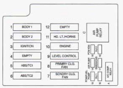
| Fuse | Usage |
| 1 | Circuit Breakers: 3,4; I/P Fuses: 36, 37, 38, 39, 40 |
| 2 | Circuit Breaker: 2; I/P Fuses: 21, 22, 26, 27, 28, 29, 33, 34, 35 |
| 3 | Concealed Fuse; I/P Fuses: 8, 9, 10, 11, 12, 13, 14, 15, 24; Underhood Electrical Center: 15, 16, 17, 18 |
| 5 | ABS/TCS Brake Pressure Modulator Valve |
| 6 | ABS/TCS Brake Pressure Modulator Valve |
| 7 | Secondary Engine Cooling EmRelay |
| 8 | Primary Engine Cooling Fan Relay |
| 9 | Automatic Level Control Air Compressor |
| 10 | Engine Compartment Fuses: 13, 14 |
| 11 | Circuit Breaker: 5; I/P Fuses: 31, 32 |
| 13 | Fuel Pump Relay, Powertrain Control Module (PCM) |
| 14 | Secondary Air Injection (AIR) Pump Relay |
| 15 | Prowertrain Control Module (PCM), Ignition Coil |
| 16 | Fuel Injectors Cylinders 1, 4, 6, 7 |
| 17 | Exhaust Gas Recirculation (EGR), Vacuum Control Signal Solenoid Valve, Secondary Air Injection (AIR), Pump Relay (Coil), Mass Air Flow Sensor, Electronic Transmission, Left and Right Heated Oxygen Sensors, Evaporative Emission (EVAP) Canister Purge Solenoid Valve |
| 18 | Fuel Injectors Cylinders 2, 3, 5, 8 |
| A | A/C Compressor Relay |
| C | Secondary Air Injection (AIR) Pump Relay |
WARNING: Terminal and harness assignments for individual connectors will vary depending on vehicle equipment level, model, and market.