Chevrolet Corvette (1998) – fuse box diagram
Year of production: 1997
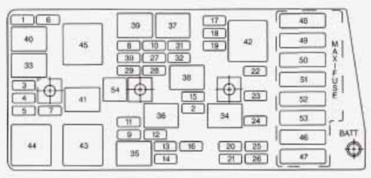
Instrument panel fuse block
The interior fuse center is on the right side of your instrument panel. Turn the knob and pull the door to access the fuses.
| Fuses | Usage |
| 1 | Console Cigarette Lighter |
| 2 | Monitored (Inadvertent) Load Control |
| 3 | Lumbar Seat |
| 4 | Driver Seat Control Module |
| 5 | Radio |
| 6 | Parking Lamps, Taillamps |
| 7 | Cigar Lighter |
| 8 | Stop Hazard Flashers |
| 9 | Body Control Module |
| 10 | Windshield Wiper/Washer |
| 11 | Accessory Power |
| 12 | Blank |
| 13 | Body Control Module |
| 14 | Crank |
| 15 | Hazard/Turn Signal |
| 16 | Air Bag |
| 17 | TONN REL (Convertible Only) |
| 18 | HVAC Controls |
| 19 | Instrument Panel Control |
| 20 | Cruise Control |
| 21 | Brake Transmission Shift Interlock |
| 22 | Body Control Module – Ignition 3 |
| 23 | Body Control Module – Ignition 2 |
| 24 | Radio Antenna |
| 25 | Body Control Module – Ignition I, Instrument Panel Control |
| 26 | Hatch/Trunk Release |
| 27 | HVAC Controls |
| 28 | Bose Speakers |
| 29 | Diagnostic |
| 30 | Right Door Control Module |
| 31 | Power Feed Door Right |
| 32 | Fuel Tank Door |
| 33 | Door Control Module Left |
| 34 | Power Feed Door Left |
| 35 | Driver Power Seat (Circuit Breaker) |
| 36 | Passenger Power Seat (Circuit Breaker) |
| 37 | Micro Relay – Monitored (Inadvertent) Load Control |
| 38 | Micro Relay – Right Daytime Running Lamp |
| 39 | Micro Relay – Hatch Release |
| 40 | Micro Relay -Left Daytime Running Lamp |
| 41 | TONN REL (Convertible Only) |
| 42 | Micro Relay – Courtesy Lamps |
| 43 | Bose Mini Relay – Speakers |
| 44 | Mini Relay – Rear Defogger |
| 45 | Maxifuse – Ignition 2 |
| 46 | Maxifuse – Rear Defogger |
| 47 | Blank |
| 48 | Maxifuse – Ignition |
| 49 | Maxifuse – Blower Motor |
| 50 | Starter |
| 51 | Blank |
| 52 | Maxi Circuit Breaker – Headlamps |
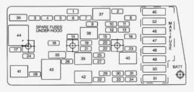
Engine compartment fuse block
There is one fuse block in the engine compartment located on the passenger’s side of the vehicle in front of the battery.
| Fuse | Usage |
| 1 | ABS TRANS |
| 2 | Approach |
| 3 | Right Headlamp Motor |
| 4 | Left Headlamp Motor |
| 5 | BLANK |
| 6 | Fog Lamp |
| 7 | Selective Real Time Damping |
| 8 | Headlamp Low Beam Right |
| 9 | Headlamp High Beam Right |
| 10 | Headlamp Low Beam Left |
| 11 | Horn |
| 12 | Headlamp High Beam Left |
| 13 | Fuel Pump |
| 14 | Cooling Fan – Ignition 3 |
| 15 | Oxygen Sensor |
| 16 | Powertrain Control Module |
| 17 | Throttle Control |
| 18 | Injector 2 |
| 19 | Engine Ignition |
| 20 | Blank |
| 21 | Blank |
| 22 | Injector 1 |
| 23 | Powertrain Control Module |
| 24 | Air Conditioning |
| 25 | Blank |
| 26 | Blank |
| 27 | Spare |
| 28 | Spare |
| 29 | Spare |
| 30 | Spare |
| 31 | Spare |
| 32 | Spare |
| 33 | Micro Relay – Air Pump |
| 34 | Micro Relay – Air Conditioner and Clutch |
| 35 | Micro Relay – Fuel Pump |
| 36 | Micro Relay – Horn |
| 37 | Micro Relay – Rear Fog Lamp |
| 38 | Micro Relay – Back-up Lamps |
| 39 | Micro Relay – Fog Lamp |
| 40 | Micro Relay – AIR Solenoid |
| 41 | Micro Relay – Selective Real Time Damping |
| 42 | Mini Relay – Ignition |
| 43 | Mini Relay – Cooling Fan 2 |
| 44 | Mini Relay – Cooling Fan 3 |
| 45 | Mini Relay – Cooling Fan 1 |
| 46 | Maxi Fuse – Cooling Fan 2 |
| 47 | Blank |
| 48 | Blank |
| 49 | Maxi Fuse – Cooling Fan 1 |
| 50 | Maxi Fuse – Air Pump |
| 51 | Blank |
| 52 | Maxi Fuse – Anti-Lock Brakes |
| 53 | Anti-Lock Brakes and Selective Real Time Damping Electronics |
| 54 | Fuse Puller |
WARNING: Terminal and harness assignments for individual connectors will vary depending on vehicle equipment level, model, and market.