Chevrolet Corvette C3 (1978 – 1982) – fuse box diagram
Year of production: 1978, 1979, 1980, 1981, 1982
Fuse Box diagram
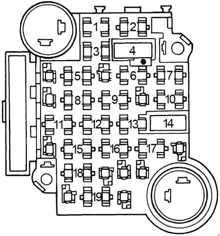
| No. | A | Circuit Protected |
| 1 | 5 | ’78-’79: Instrument panel lights |
| 7.5 | ’80-’82: Instrument panel lights | |
| 2 | – | – |
| 3 | – | – |
| 4 | 30 | Circuit breaker: Power windows |
| 5 | – | – |
| 6 | 25 | Heater and air conditioner |
| 7 | 10 | ’80-’82: Electronic Control Module |
| 8 | – | – |
| 9 | 25 | Windshield wipers and washers |
| 10 | 20 | Stop and hazard lights, key warning buzzer |
| 11 | 10 | ’78-’79: Gauges, telltale lights, cruise control, seat belt buzzer, power window relay |
| 20 | ’80-’82: Gauges, warning lights, seat belt buzzer light, power window relay, cruise control | |
| 12 | 20 | ’78-’79: Tail, side marker, parking and underhood lights |
| 30 | ’80-’82: Parking, side marker, engine compartment and tail lights | |
| 13 | 20 | ’78-’79: Radio, rear window defogger |
| 10 | ’80-’82: Radio | |
| 14 | 30 | ’80-’82: Circuit breaker: Power accessories |
| 15 | 20 | Turn signals and backup lights |
| 16 | 20 | Clock, cigar lighter, anti-theft alarm, dome light, courtesy light, glove box light, glove box light, power antenna (’80-’82), horn relay (’80-’82), power door locks (’80-’82) |
| 17 | 30 | ’80-’82: Auxiliary cooling fan |
| 18 | – | – |
| 19 | – | – |
| Circuit Breaker: Headlights — Circuit breaker is integral with headlight switch to protect headlight circuit ’80-’82: Power Seats, Power Windows & Power Door Locks — Circuit breaker is located on fuse panel to protect power accessories. Fusible Links: Fusible links are located in the engine compartment. Gauge size is marked on insulation and color matches wire being fused. Fusible links should always be four gauge sizes smaller than wire being fused The links are: | ||
WARNING: Terminal and harness assignments for individual connectors will vary depending on vehicle equipment level, model, and market.