Chevrolet Express (2003 – 2005) – fuse box diagram
Year of production: 2003, 2004, 2005
Floor Console Fuse Block
The floor console fuse block is located under the driver’s seat.
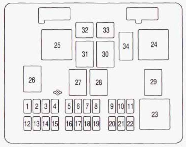
| Fuse | Usage |
| 1 | Spare |
| 2 | Outside Rear View Mirror |
| 3 | Courtesy Lamp/SEO |
| 4 | Left Rear Stop/Turn Signal |
| 5 | Cargo Locks |
| 6 | Right Rear Stop/Turn Signal |
| 7 | Driver Locks |
| 8 | Stop/Center High Mounted Stop Lamp |
| 9 | Climate Control 1 |
| 10 | Climate Control |
| 11 | Brakes |
| 12 | Heated Mirror/Defogger |
| 13 | Right Rear Blower |
| 14 | Driver Turn Mirror |
| 15 | Door Locks |
| 16 | Upfitter Park |
| 17 | Not Available |
| 18 | Left Rear Park Lamp |
| 19 | Pass Turn Mirror |
| 20 | Right Rear Park Lamp |
| 21 | Trailer Park Lamp |
| 22 | Front Park Lamp |
| 32 | Auxilary 1 |
| 33 | Auxilary 2 |
| Relays | Usage |
| 23 | Window Residual Accessory Power |
| 24 | Auxiliary |
| 25 | Right Rear Defogger |
| 26 | Courtesy Lamp |
| 27 | Cargo Unlock |
| 28 | Driver Unlock |
| 29 | Park Lamp |
| 30 | Door Locks |
| 31 | Pass Unlock |
| Circuit Breaker | Usage |
| 34 | Power Window |
Engine Compartment Fuse Relay Center
The fuse block is in the engine compartment on the driver’s side of the vehicle.
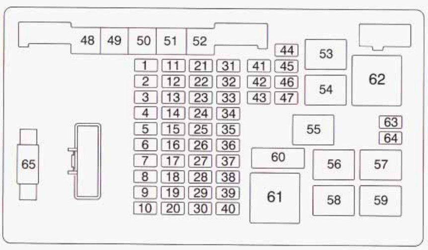
| Fuse | Usage |
| 1 | Radio Battery |
| 2 | Powertrain Control Module Battery |
| 3 | Left Rear Turn Lamp |
| 4 | Right Rear Turn Lamp |
| 5 | Backup Lamps Trailer Wiring |
| 6 | Ignition 0 |
| 7 | Stop Lamp |
| 8 | Right Rear Defogger/Heated Mirror |
| 9 | Right Daytime Running Lamp/Turn Signal |
| 10 | Left Daytime Running Lamp/Turn Signal |
| 11 | Truck Body Control Module 4 |
| 12 | Fuel Pump |
| 13 | Trailer |
| 14 | Flasher |
| 15 | Horn |
| 16 | Truck Body Control Module 3 |
| 17 | Trailer Stop/Turn Signal |
| 18 | Truck Body Control Module 2 |
| 19 | Truck Body Control Module |
| 20 | Remote Function Actuator |
| 21 | Engine 2 |
| 22 | Ignition E |
| 23 | Engine 1 |
| 24 | Truck Body Control Module Ignition 1 |
| 25 | Spare |
| 26 | RPA/lnside Rearview Mirror |
| 27 | Crankcase |
| 28 | Brake Transmission Shift Interlock System |
| 29 | Auxiliary Power Outlets |
| 30 | Cigarette Lighter |
| 31 | Instrument Panel Cluster |
| 32 | Air Conditioning |
| 33 | Spare |
| 34 | Vent |
| 35 | Spare |
| 36 | Vehicle Back Up |
| 37 | Supplemental Inflatable Restraint System |
| 38 | Powertrain Control Module Ignition I |
| 39 | Oxygen Sensor B |
| 40 | Oxygen Sensor A |
| 41 | Windshield Wipers |
| 42 | Right Headlamp – Low Beam |
| 43 | Left Headlamp – Low Beam |
| 44 | Left He45adlamp – High Beam |
| 45 | Right Headlamp – High Beam |
| 46 | Truck Body Control Module-Accessory |
| 47 | Front Windshield Wiper |
| 48 | Anti-Lock Brakes |
| 49 | Ignition A |
| 50 | Trailer |
| 51 | Climate Control Blower |
| 52 | Ignition B |
| 63 | Spare |
| 64 | Spare |
| Relays | Usage |
| 53 | Windshield Wiper |
| 54 | Air Conditioning |
| 55 | Spare |
| 56 | Headlamp – High Beam |
| 57 | Fuel Pump |
| 58 | Headlamp – Low Beam |
| 59 | Horn |
| 61 | Starter |
| 62 | Spare |
| Circuit Breaker | Usage |
| 60 | Power Window |
WARNING: Terminal and harness assignments for individual connectors will vary depending on vehicle equipment level, model, and market.