Chevrolet Malibu (1997 – 2003) – fuse box diagram
Year of production: 1997, 1998, 1999, 2000, 2001, 2002, 2003
Passenger Compartment Fuse Box (Left)
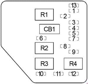 Chevrolet Malibu – fuse box diagram – passenger compartment (left)
No.
| A
| Protected Component |
| 1 | 25 | Wipers, Multifunction Switch |
| 2 | 10 | Trunk Release, Remote Keyless Entry |
| 3 | 10 | Turn Sigals |
| 4 | 10 | Power Mirrors |
| 5 | 10 | Air Bag (Sensing & Diagnostic Module (SDM)) |
| 6 | 10 | Body Control Module (BCM) |
| 7 | 10 | Powertrain Control Module (PCM) |
| 8 | 15 | Power Door Lock |
| 9 | 10 | Instrument Panel Cluster, Body Control Module |
| 10 | 15 | Stop Lamps |
| 11 | 10 | Hazard Lamps |
| 12 | 10 | Climate Control, Cluster, Data Link Connector |
| 13 | 10 | Radio |
| Relay |
| R1 | Trunk Release |
| R2 | Power Door Lock (Unlock) |
| R3 | Power Door Lock (Lock) |
| R4 | Driver Door Unlock |
| Circuit Breaker |
| CB1 | Power Seat |
Passenger Compartment Fuse Box (Right)
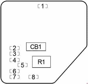 Chevrolet Malibu – fuse box diagram – passenger compartment (right)
No.
| A
| Protected Component |
| 1 | 10 | Interior Lamps (Dimming) |
| 2 | 2 | Cruise Control Switch |
| 3 | 20 | Climate Control |
| 4 | 10 | Cruise Control Module, Brake Switch, Body Control Module (BCM) |
| 5 | 10 | Fog Lamps |
| 6 | 10 | Interior Lamps (Non-Dimming) |
| 7 | 10 | Radio, Clock |
| 8 | 20 | Sunroof |
| Relay |
| R1 | Fog Lamps |
| Circuit Breaker |
| CB1 | Power Windows |
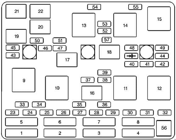
Engine Compartment Fuse Box
 Chevrolet Malibu – fuse box diagram – engine compartment
No.
| A
| Protected Component |
| 1 | 30 | Ignition Switch |
| 2 | 30 | Passenger Compartment Fuse Box (Right (Fuse: “1”, “5”, “6”)) |
| 40 | Passenger Compartment Fuse Box (Left (Fuse: “2”, “4”, “8”, “CB1”) |
| 3 | 30 | Passenger Compartment Fuse Box (Left (Fuse: “6”, “10”, “11”, “12”) |
| 4 | 50 | ABS |
| 30 | Passenger Compartment Fuse Box (Right (Fuse: “1”, “5”, “6”)) |
| 5 | 40 | Ignition Switch |
| 6 | 30 | Air Pump |
| 7 | 40 | Passenger Compartment Fuse Box (Left (Fuse: “2”, “4”, “8”, “CB1”) |
| 40 | ABS |
| 8 | 30 | Cooling Fan No.1 (Left) |
| 23 | – | – |
| 24 | – | – |
| 25 | – | – |
| 26 | – | – |
| 27 | – | – |
| 28 | – | – |
| 29 | – | – |
| 30 | – | – |
| 31 | – | – |
| 32 | – | – |
| 33 | 30 | Rear Window Defogger |
| 34 | 20 | Cigar Lighter, Accessory Power Outlets |
| 35 | 10 | Generator |
| 10 | ABS |
| 36 | 15 | ABS |
| 37 | 10 | Air Conditioning Compressor, Body Control Module (BCM) |
| 38 | 10 | Automatic Transaxle |
| 39 | 10 | Powertrain Control Module (PCM), Ignition |
| 40 | 10 | ABS, ABS Relay |
| 41 | 10 | Ignition Control Module |
| 42 | 10 | Back-Up Lamps, Automatic Transaxle Shift Lock Control System |
| 43 | 15 | Horn |
| 44 | 10 | Powertrain Control Module (PCM), Mass Air Flow (MAF) Sensor |
| 45 | 15 | Parking Lamps |
| 46 | 10 | Climate Control System, Air Temperature Actuator, Daytime Running Lamps Relay, Rear Window Defogger Relay |
| 47 | 10 | Evaporative Emission (EVAP) Canister Purge Valve, Evaporative Emission (EVAP) Canister Vent Solenoid, Powertrain Control Module (PCM), Heated Oxygen Sensors |
| 48 | 15 | Fuel Pump Relay, Fuel Injectors |
| 49 | 10 | Generator |
| 50 | 15 | Right Headlamp |
| 51 | 15 | Left Headlamp, Automatic Lamp Control Relay |
| 52 | 15 | Cooling Fan No.2 (Right) |
| 53 | 30 | Blower Motor Relay |
| 54 | – | – |
| 55 | 15 | Cooling Fan No.2 (Right) |
| 56 | – | Fuse Puller |
| 57 | – | ’97-: j Tach Test Point for Diagnostic Testing |
| Relay |
| 9 | Rear Window Defogger |
| 10 | – |
| 11 | ABS |
| 12 | Cooling Fan No.1 |
| 13 | Blower Motor |
| 14 | Cooling Fan No.2 |
| 15 | Cooling Fan |
| 16 | Air Conditioning Compressor |
| 17 | – |
| 18 | Fuel Pump |
| 19 | Automatic Lamp Control |
| 20 | Automatic Lamp Control |
| 21 | Horn |
| 22 | Daytime Running Lamps (DRL) |
| Circuit Breaker |
| CB1 | Power Windows |
WARNING: Terminal and harness assignments for individual connectors will vary depending on vehicle equipment level, model, and market.