Chevrolet Uplander (2006) – fuse box diagram
Year of production: 2006
Instrument Panel Fuse Block
The instrument panel fuse block is located under the instrument panel on the passenger’s side of the vehicle.
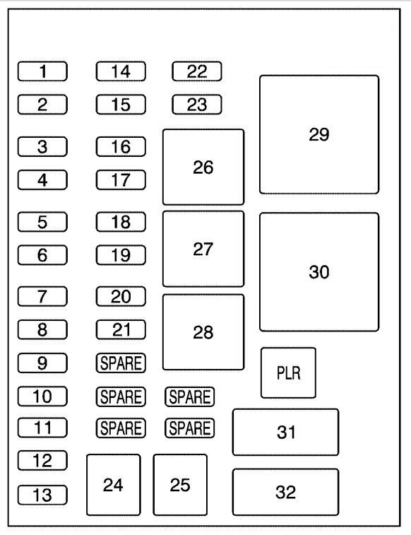
| Fuses | Usage |
| 1 | Trunk, Door Locks |
| 2 | Electronic Level Control |
| 3 | Rear Wiper |
| 4 | Radio Amplifier |
| 5 | Interior Lamps |
| 6 | OnStar® |
| 7 | Keyless Entry Module |
| 8 | Cluster, Heating, Ventilation, Air-Conditioning |
| 9 | Cruise Switch |
| 10 | Steering Wheel Illumination |
| 11 | Power Mirror |
| 12 | Stoplamp, Turn Lamps |
| 13 | Heated Seats |
| 14 | Blank |
| 15 | Electronic Level Control |
| 16 | Heated Mirror |
| 17 | Center High-Mounted Stoplamp, Back-up Lamps |
| 18 | Blank |
| 19 | Canister Ventilation |
| 20 | Park Lamps |
| 21 | Power Sliding Door |
| 22 | Blank |
| 23 | Blank |
| 24 | Left Power Sliding Door |
| 25 | Right Power Sliding Door |
| Relays | Usage |
| 26 | Blank |
| 27 | Blank |
| 28 | Park Lamps |
| 29 | Retained Accessory Power |
| 30 | Rear Defog |
| PLR | Fuse Puller |
| Circuit Breaker | Usage |
| 31 | Power Seats |
| 32 | Power Window |
Underhood Fuse Block
The underhood fuse block is located in the engine compartment.
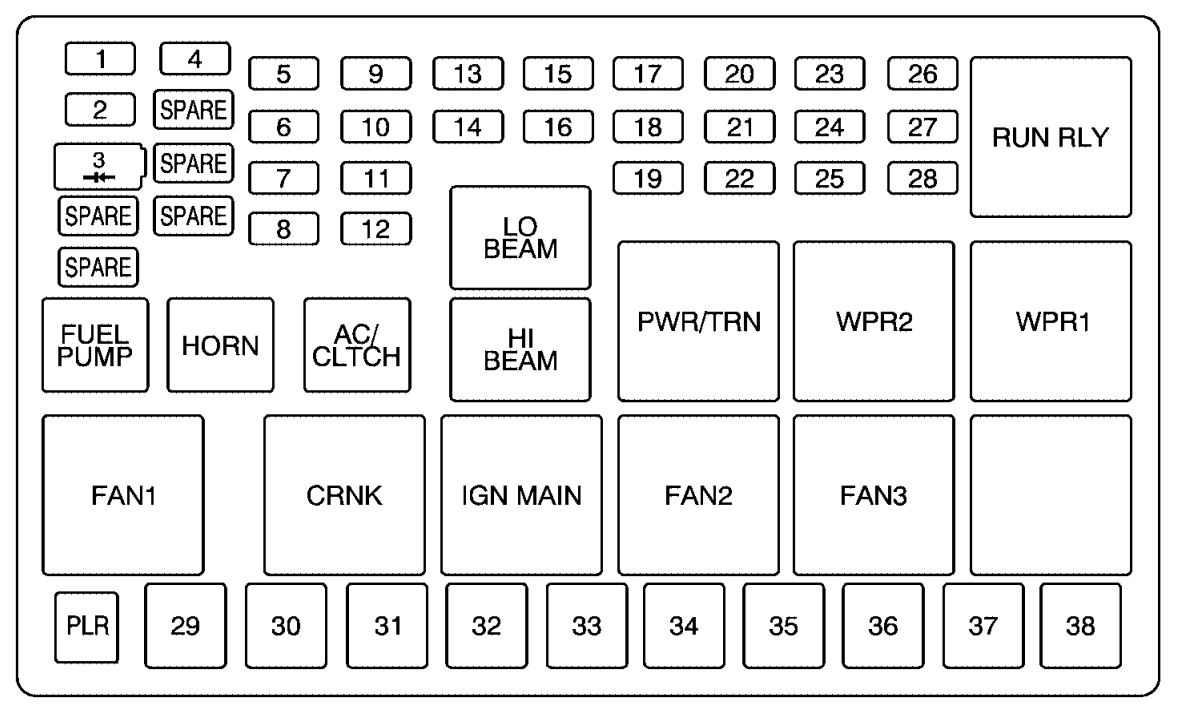
| Fuses | Usage |
| 1 | Right High Beam |
| 2 | Fuel Pump |
| 3 | Diode |
| SPARE | Spare |
| SPARE | Spare |
| 4 | Left High Beam |
| SPARE | Spare |
| SPARE | Spare |
| SPARE | Spare |
| 5 | Not Used |
| 6 | Air Conditioning Clutch |
| 7 | Horn |
| 8 | Left Low Beam |
| 9 | Powertrain Control Module, Electronic Throttle Control |
| 10 | Not Used |
| 11 | Transmission Solenoid |
| 12 | Right Low Beam |
| 13 | Anti-lock Brake System |
| 14 | Powertrain Control Module Ignition |
| 15 | Electronic Ignition |
| 16 | Fuel Injector |
| 17 | Climate Control, RPA, Cruise Control |
| 18 | Electronic Throttle Control |
| 19 | Engine Sensor, Evaporator |
| 20 | Airbag |
| 21 | Not Used |
| 22 | Emission, All-Wheel Drive |
| 23 | Auxiliary Power |
| 24 | Front Windshield Washer |
| 25 | AC/DC Inverter |
| 26 | Rear Blower |
| 27 | Front Blower |
| 28 | Front Windshield Wiper |
| J-Case Fuses | Usage |
| PLR | Fuse Puller |
| 29 | Fan 1 |
| 30 | Starter Solenoid |
| 31 | Anti-lock Brake System Motor |
| 32 | Blank |
| 33 | Fan 2 |
| 34 | Front Blower High |
| 35 | Battery Main 3 |
| 36 | Rear Defogger |
| 37 | Battery Main 2 |
| 38 | Spare |
| Relays | Usage |
| RUN RLY | Starter |
| LO BEAM | Low Beam |
| FUEL PUMP | Fuel Pump |
| HORN | Horn |
| AC/CLTCH | Air-Conditioning Clutch |
| HI BEAM | High Beam |
| PWR/TRN | Powertrain |
| WPR2 | Wiper 2 |
| WPR1 | Wiper 1 |
| FAN 1 | Fan 1 |
| CRNK | Crank |
| IGN MAIN | Ignition Main |
| FAN2 | Fan 2 |
| FAN3 | Fan 3 |
| BLANK | Not Used |
WARNING: Terminal and harness assignments for individual connectors will vary depending on vehicle equipment level, model, and market.